What to measure?
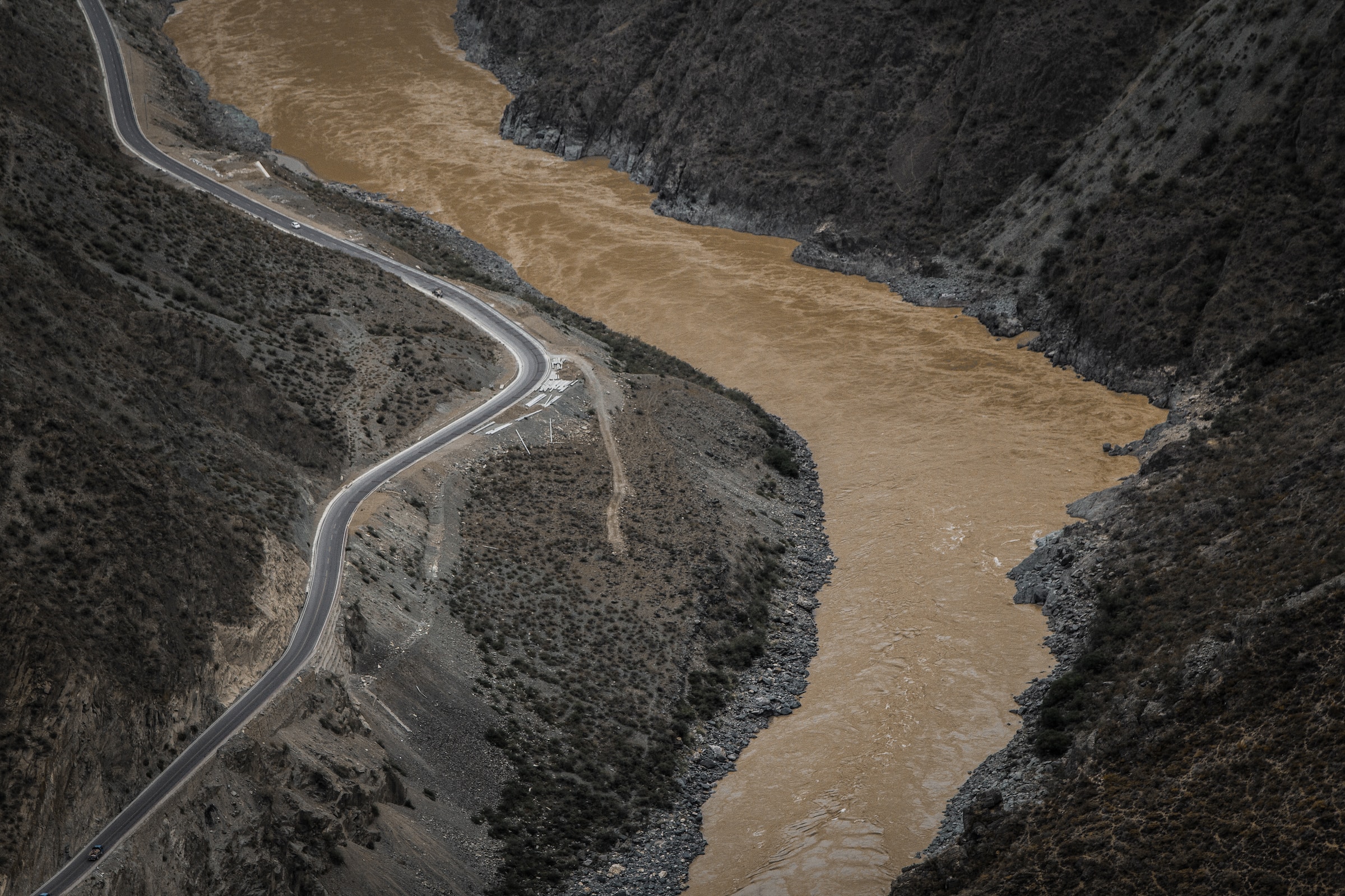
We want to understand what’s the visibility in the water - is it milky, muddy, with silt… general color of the murkiness would be good to get - brown-milky is way worse than white-bluish milky.
We also want to understand what’s the flow - is water completely still or is it moving a bit. Maybe too much for diving?
what alse?
Temperature sounds like a low-hanging fruit, though it’s a question if you’ll make any difference between 6°C and 8°C water. On the other hand, outside (air) temperature is quite useful information.
While we’re at outside temperature, we might want to know the barometric pressure to be able to calculate dew point - again, interesting to know if you’ll be welcomed with frost / dew or you’ll have dry (and warm) entry in the water.
Water level might also be a good idea for springs that fluctuate during the year. I still remember day-long drive to Montenegro to discover water level more than 15m higher than expected in one of the estavellas we were trying to explore.
Of course, device own telemetry is essential to be collected - battery level, battery temperature, signal quality, power/charging levels, ambient light levels and anything else that we can pick up that will not only make a nice graph, but also will tell us if device might need a service or a replacement.
If we’re in good reception area, we also might want to position low-res camera to capture picture of the water source, to complete the understanding.
How to measure
Turbidity
Visibility in water is a complicated topic, but in scientific terms, it’s called “turbidity” and is measured by observing a drop in light transmittance through water column, compared to precalibrated values. This is done by placing a source of light on one side of the device, light received on the other and calibrating a device in distilled water. Any water with any suspension in it will shine less light and that drop will tell us how bad is it.
To measure this, we’ll need a light source and a light-sensitive receiver.
For light source, almost any LED will do good, but I decided to use single WS2812 RGB-NW LED. Why? First, it is a multi-color LED so it can give us readings on at least 3 discreet wavelength, not only telling us how murky water it is, but also giving us the idea of “color” of that murkiness. With this, we can determine if water is milky-blue, muddy-brown or crystal-blue. Then, it is digitally controllable over a single digital GPIO pin, making it a perfect candidate for cheap MCU choice. Finally, as extra bonus, it allows us to check the intensity drop curve on different light volumes - we can maybe learn something by shining LED at 25%, 50%, 75% and 100% and learning if receiving light is also proportional to that.
Direct measurement can tell us overall murkiness of the water, but will not tell us if suspended matter is large (pieces of leaves, for example) or small (like in milk). Measuring backscatter will give us some hints about the size, so we’ll need not one but two light-sensitive receivers.
First choice is to use one of the I2C enabled, easy to read, temperature compensated, lux calibrated, all-singing, all-dancing modules, like TSL2501 or VEML6030, or… but they cost few bucks per piece and will drive total price en mass. Instead I decided to sacrifice 2 analog GPIO inputs from MCU, using regular ultra-cheap photoresistors.
Tricky part is assembling all of this - to measure backscatter, we should measure intersection of a 15° cone of light shining from LEDs and 15° cone of light coming to photo resistor. Rest of the light (secondary backscatter) should be discarded or attenuated so it doesn’t interfere with the measurement.
Flow
This is the tough part to measure.
Easiest way is to place a “wheel” and rotary encoder and count number of spins per second. Problem with “wheel” is that it can break or jam, and will generally reach a speed limit very soon. Magnetic rotary encoders are not a problem and this method can easily be implemented. Good side of this option is the fact that wheel can be isolated from the electronics and this would not require waterproof shafts or orings for sealing.
Another possibly better option is to suspend a free moving, relatively heavy rod from the in-water sensor and measure its angle offset from the vertical, as indication of water flow. Angle can be measured by angular hall sensor and a magnet and, like with previous option, sealing is not a problem.
Most accurate, most robust but also most expensive option of measuring water flow would be using ultrasonic sensor arrays, similar to what ultrasonic anemometers are using. These would measure doppler effect of moving water and would determine speed based on that. They can be tuned and calibrated for absolute measurement (m/s) but sensors are hard to find and are way over the imaginary budget. For future reference and some rich folks, you’d need waterproof 3-8Mhz transducers (with appropriate excitation / pickup electronics). I’ve found some transducers for $30-$50 a piece, which IMHO is too much.
None of the options, however, offer electricity generation capabilities, so I started thinking about a smarter take on the “wheel” option, where speed of spinning would be an indication of a water flow, but same flow would be used to create energy needed for sensors operation. Rotary would be a Tyson turbine shaped “nose” with a set of permanent magnets, while coils would be dipped in epoxy and thus would not require a sealed shaft for sealing. Nose would spin in front of the rest of the device, placed on a guide central rail. Generated electricity would be an indication of water flow and, due to magnetic resistance, would have wider linear range than a simple wheel. Still, durability and robustness remains a challenge.
Temperature
Temperature is quite easy to measure - number of accurate, calibrated and easy to use sensors exist, starting from analog-output LM35, over 1-wire DS18b20, to a plethora of I2C enabled sensors. While one of the design goals is to keep things as cheap as possible, I also want to keep things simple and clean, so I decided to go with 1-wire DS18b20 for in-water part of the probe - it’s small, cheap, proven, works great and has minimal software overhead for interfacing.
Above-the-water probe can use of the more fancier BMPx80 sensors - they offer temperature, humidity and sometimes barometric pressure, all in the pack of a single chip with I2C interface.
Water level
Water level can be measured by placing ultrasonic range finders above the water. As water level rises, they would measure shorted distances and vice versa. This approach has number of problems - range finders are typically not water proof, you might not always be able to mount the comms box directly above the water and so on.
Another approach is to measure water level by in-water probe, using a depth meter, either a proper sensor (expensive) or a selection of cheaper wheatstone bridges.
My best candidate so far is cheap Aliexpress MD-PS002 (rated to, say, 700kPa) in combination with HX711 and some silicone membrane - it’s a wheatstone bridge based sensor (weight scale) and silicone will act as a protective membrane. If that fails, I’ll try resistive films and proper pressure transmitting mechanics, before either dropping the idea, or switching to expensive integrated depth sensors.


Comments